
On-Site Dynamic Balancing
On-site dynamic balancing of fans, rotors and impellers
Single- and two-plane balancing carried out in the machine's own bearings and installed condition, avoiding rotor removal and workshop time.
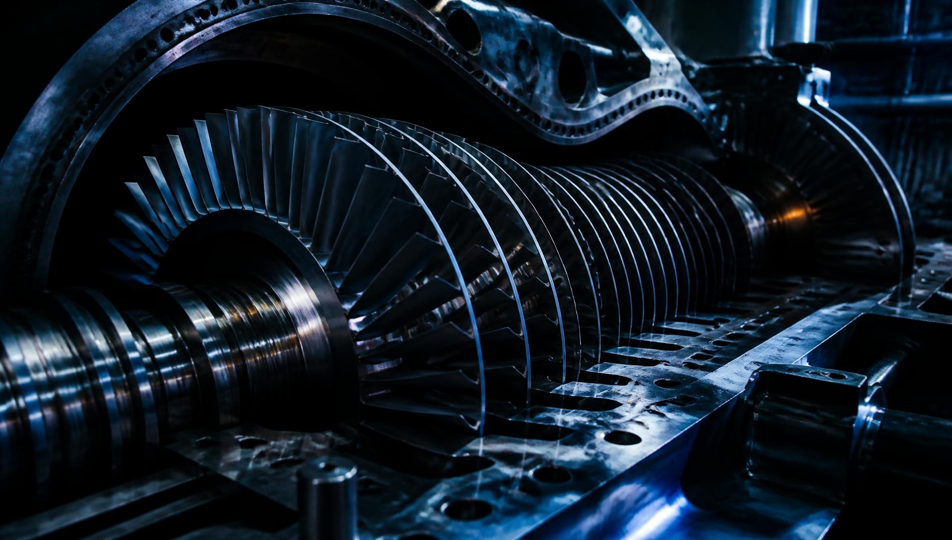
Unbalance is the most common cause of high vibration on fans and other large rotors, and it is one of the few faults that can be corrected on the spot. Balancing in situ keeps the rotor in its own bearings and its own support structure, which means the correction accounts for the real installed condition rather than a workshop stand.
The work begins with diagnosis, not weights. A dominant 1x running speed component with stable phase points to unbalance; the same amplitude with unstable phase, or with strong harmonics, points elsewhere. Bolting weights onto a machine with a bearing defect, a resonance problem or a bent shaft wastes a shift and hides the real fault, so the balance is only attempted once the diagnosis supports it.
Correction is then carried out using influence coefficient method with trial weights, typically achieving a residual well inside the relevant ISO 21940 balance quality grade. Before and after readings are recorded so the improvement is documented rather than asserted.
Typical reasons for balancing
- Process build-up or erosion on fan and impeller blades
- Material loss following a blade repair or partial replacement
- Vibration after a rebuild, re-blading or coupling change
- Repeat bearing failures traced to a persistent 1x component
- Excessive structural vibration limiting plant output
- Commissioning a new or refurbished rotor in situ
What you receive
- Diagnostic confirmation that unbalance is the dominant fault
- Before and after vibration readings in every measurement axis
- Recorded weight positions, masses and radii for future reference
- Residual unbalance assessed against ISO 21940 quality grades
- Notes on any secondary faults found while on the machine
- Recommended monitoring interval to detect further build-up
Worked example
How a two-plane balance runs
A worked walk-through of the sequence on a typical induced draught fan, using representative figures. It shows what is measured, what is fitted, and how the result is proven.
Target: G 6.3 · 850 kg rotor · 1,480 rev/min
01
Reference run
Machine run at normal operating speed and load. Amplitude and phase recorded at both bearings, in three axes.
- Drive end, 1x
- 11.4 mm/s @ 71°
- Non-drive end, 1x
- 8.2 mm/s @ 118°
02
Confirm it is unbalance
1x dominant, phase steady across runs, no significant harmonics and no bearing tones under enveloping. Misalignment, looseness and resonance ruled out before any weight goes on.
- 1x share of overall
- 88%
- Phase drift over 3 runs
- ±2°
03
Trial weight, plane 1
A known trial mass is fitted at a known radius and angle. The change in amplitude and phase gives the influence coefficient for that plane.
- Trial mass fitted
- 120 g @ 380 mm, 0°
- Drive end response
- 9.1 mm/s @ 34°
04
Trial weight, plane 2
Trial weight moved to the second plane and the run repeated, giving the cross-effect between planes. Both coefficients are needed to solve a two-plane correction.
- Trial mass fitted
- 120 g @ 380 mm, 0°
- Non-drive end response
- 6.4 mm/s @ 165°
05
Correction fitted
The influence coefficient solution gives the mass and angle for each plane. Weights are fitted, secured, and their positions recorded so the job can be repeated or audited later.
- Plane 1 correction
- 214 g @ 380 mm, 47°
- Plane 2 correction
- 165 g @ 380 mm, 212°
06
Verification run
Final readings taken in the same positions and axes as the reference run, and the residual checked against the agreed balance grade before leaving site.
- Drive end, 1x
- 1.6 mm/s
- Non-drive end, 1x
- 1.3 mm/s
- Residual vs G 6.3 limit
- Inside tolerance
Balanced on site, or sent to a workshop
The same rotor, the same unbalance, two routes. This is the difference in-situ balancing actually makes, and it is why we lead with it.
| Step | Rotor to a workshop | Balanced on site |
|---|---|---|
| Isolate, strip down, remove the rotor | 1–2 days, usually a crane or lifting plan | Not required |
| Transport each way | Haulage cost, plus handling damage risk | Not required |
| Workshop queue | Days to weeks, outside your control | Not required |
| Balancing itself | On a workshop stand, not the real support | In its own bearings and structure |
| Refit, realign, recommission | 1–2 days, alignment done again | Not required |
| Typical total downtime | 1–3 weeks | A single shift |
Timings are indicative for a large process fan and will vary with access, lifting requirements and workshop availability.
ISO 20816 severity zones, mm/s RMS
86% reduction — zone D to zone A, corrected in situ.
Balance quality grades
ISO 21940-11 sets the permissible residual unbalance for a rotor by machine class. The grade agreed before the work starts is the grade the finished residual is measured against.
| Grade | eper · ω (mm/s) | Typical rotor class |
|---|---|---|
| G 0.4 | 0.4 | Precision grinder spindles, gyroscopes |
| G 1 | 1 | Machine tool drives, small armatures |
| G 2.5 | 2.5 | Gas and steam turbines, turbo-compressors, machine tool drives |
| G 6.3 | 6.3 | Process plant fans, pump impellers, centrifuges, general machinery |
| G 16 | 16 | Drive shafts, crushers, agricultural machinery |
| G 40 | 40 | Car wheels and rims, automotive drive shafts |
Before we arrive
A balance goes quickest when these are sorted in advance. None of them are dealbreakers — tell us what you have and we will work around it.
- Safe access to both bearing housings while the machine is running at its normal operating speed.
- The ability to stop, isolate and restart the machine several times — a balance needs a trial-weight run.
- Somewhere to attach or remove correction weights: a fan hub, balancing ring, coupling or rotor disc.
- Rotor mass and normal service speed, if known, so the target balance grade can be agreed in advance.
- Recent vibration readings or maintenance history, if you have them. Helpful, but not essential.
- Site induction and any permits your safety system requires, arranged before arrival.
Permissible residual unbalance
Work out the balance tolerance for a rotor to ISO 21940-11. Enter the rotor mass, its normal service speed and the quality grade for the machine class.
- Specific unbalance eper
- 41 g·mm/kg
- Total permissible Uper
- 34,551 g·mm
- Per plane (two-plane, split evenly)
- 17,275 g·mm
- Equivalent mass at that radius
- 43 g per plane
Calculated as eper = 9549 · G / n, then Uper = eper · m. Applies to rotors in a rigid state. The even two-plane split assumes a symmetric rotor with correction planes either side of the centre of gravity; overhung and asymmetric rotors are apportioned differently. Treat this as a planning figure, not a substitute for assessing the machine.

On-Site Dynamic Balancing — common questions
Do you need to remove the rotor?
No. That is the point of balancing on site. The rotor stays in its own bearings and its own support structure, so the correction accounts for the real installed condition rather than a workshop stand — and you avoid the strip-down, the transport and the reassembly.
How long does an on-site balance take?
A straightforward single-plane job is often complete within a shift. Two-plane work on a large rotor, or a machine needing several trial runs, can take longer. The main variable is usually how quickly the machine can be stopped, weighted and restarted, not the balancing itself.
What balance quality grade can you achieve?
Correction is worked to the ISO 21940-11 grade appropriate to the machine class — commonly G 6.3 for process fans and pump impellers, G 2.5 for turbines and turbo-compressors. The residual achieved is measured and recorded against that target rather than asserted.
How do I know unbalance is actually the problem?
A dominant peak at 1x running speed with stable phase points to unbalance. The same amplitude with unstable phase, or with strong harmonics, points somewhere else — looseness, misalignment, a bearing defect or resonance. We confirm the diagnosis before fitting any weight, because balancing a machine that is not out of balance wastes a shift and hides the real fault.
The machine was balanced recently and it is bad again. Why?
Usually because something is putting the unbalance back — process build-up or erosion on the blades, a cracked or shifting component, or a thermal effect. Repeat unbalance is a symptom. Where we see it, the report addresses the underlying cause rather than just re-balancing.
Can you balance a machine that is down now?
Short-notice attendance can normally be arranged for a machine that is stopped or limiting output. Call rather than email if the plant is down — it is the quickest way to get a date confirmed.
Other services
Looking for the full picture? Return to the main capability overview.